This validation project is funded by the German Federal Ministry of Education and Research under the identifier VIP+ 03VP06431.
The members involved are based in Dresden, Germany.
Mutual synchronization at frequencies of 24 GHz and 60 GHz is validated against industrial standards, and the theoretical and circuit-design related solutions necessary are developed and designed.

In the current phase of the project we develop fully integrated BiCMOS phase-locked loop (PLL) oscillator nodes operating at 60GHz. Using these we set up networks of mutually delay-coupled PLLs. Using our current prototypes we validate robust synchronization of two PLLs at distances of up to 500 meters and operating at 24 GHz. In the following we set up a demonstrator of at least four PLLs at room scale to validate positioning with precision in the millimeter to centimeter regime. In the remaining time the scalability and modular nature of such mutual synchronization implementations will be validated.
In parallel we continuously develop the theoretical tools necessary to unravel the essential properties of synchronization in networks of mutually delay-coupled oscillators. This includes the development of analytic and numerical tools to study, characterize and risk-asses the stability of synchronized states with respect to large perturbations, node failure, temperature-drifts, and oscillator component heterogeneity.
Furthermore we actively work on precisely connecting the theoretical approaches from electrical engineering transfer-functions and dynamical systems theory. From this we deduce design templates from an electrical engineering point of view.
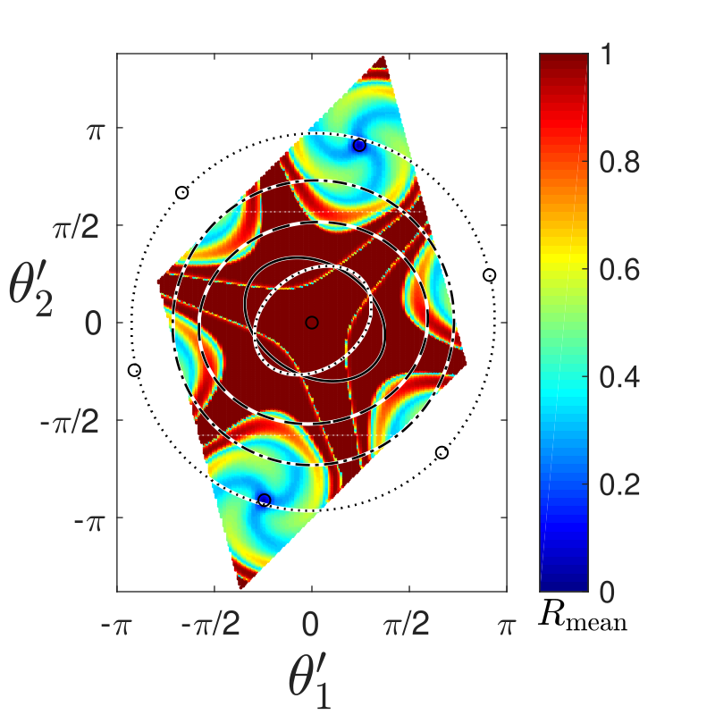
Illustration of the rich dynamics that can be observed in systems of mutually delay-coupled oscillators, Fig.1 shows a basin stability plot for a system of three oscillators delay-coupled in a ring topology. With such plots the robustness of a synchronized state to large perturbations in such systems can be analyzed. This then determines the regimes in which the system can reliably operate.
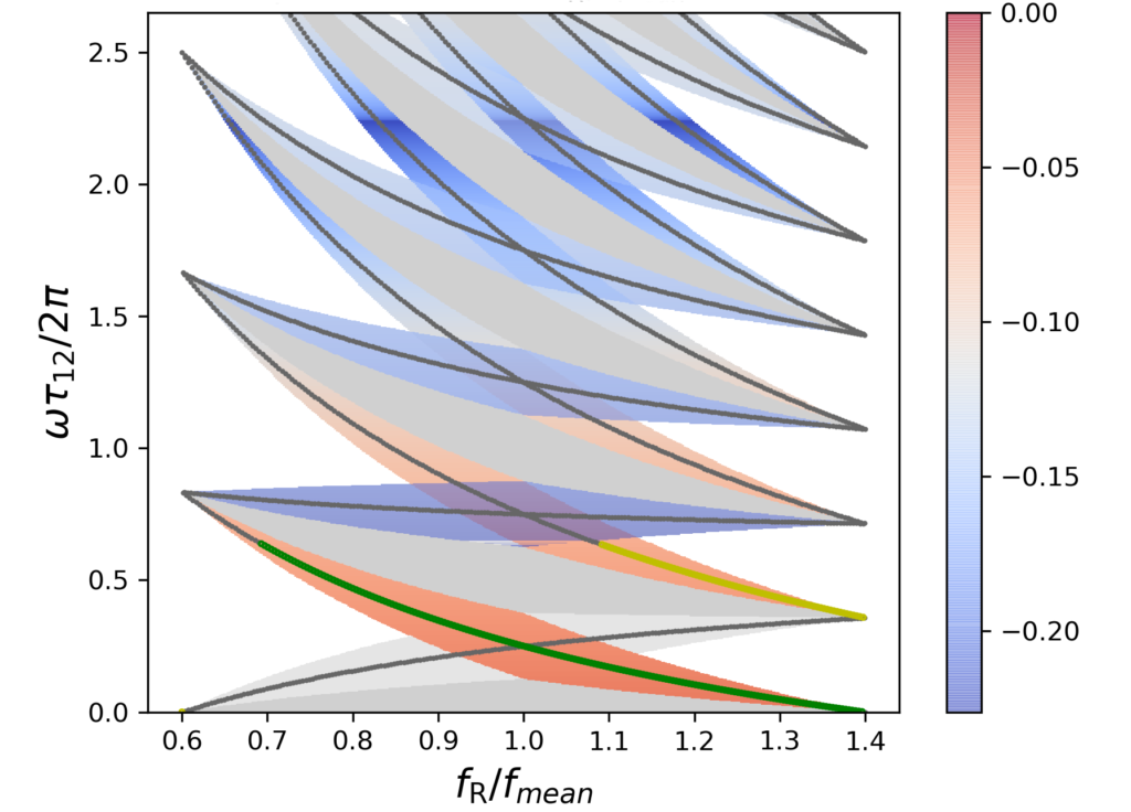
Working towards the combination of hierarchical and mutual synchronization we currently validate our theoretical models for the entrainment of mutually-coupled PLL systems in experiments in which the signaling time-delays can be controlled. Parameter plot Fig. 2 shows in color, as a function of the reference frequency and the time-delay between the two mutually coupled oscillators, where a self-organized synchronized state can be entrained by an external reference.